Recently, it is possible to trace the tendency of constant growth in demand for plate-type gasketed heat exchangers THERMAKS, which, in addition to a relatively small metal capacity, have a high heat transfer coefficient. High efficiency is due to the fact that the defining dimension in the design of the plate HE is the distance between the plates. However, there are some technological processes in which the lamellar apparatus is inferior to the classical shell-and-tube TOA due to the following features:
- Relatively small flow area of the channel, which is formed when a set of plate packs of various reliefs;
- Low maximum operating temperature due to the thermal resistance of the seal material.
- Maximum working pressure up to 25 bar.
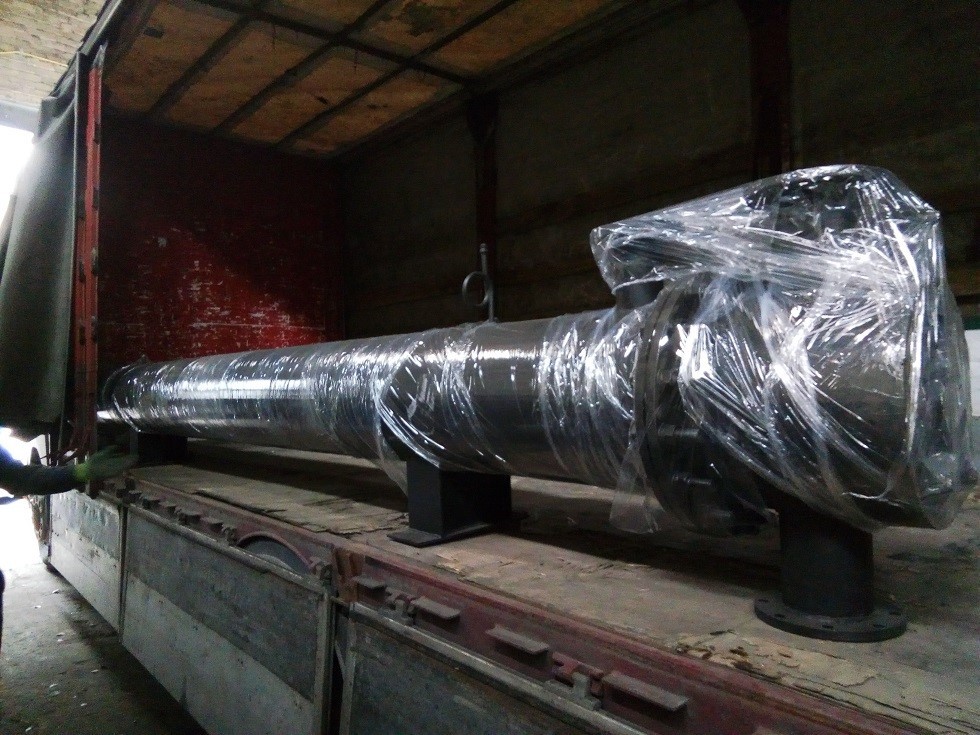
Let's take a closer look at the design and operating modes of the shell-and-tube heat exchanger , which is manufactured on the territory of the production complex of OPEKS Energosystems. We can substantively study the above issues using the example of a heat exchanger - heater OPEKS-3-LS560.40-500-HCS, which was manufactured for the largest oil extraction plant in Europe. The complexity of the task of heat transfer was the presence of small adhesive particles of husk from seeds in the oil after the press. During operation, the presence of this kind of inclusions can lead to clogging of the flow section of the channel in a standard plate HE, which makes it impossible to use it.
The design of the heat exchanger consists of the following main elements: a casing (cylindrical shell), two oil chambers, a casing cover, a bundle of heat exchange tubes. Let's go through all of the above elements in more detail to recreate the full picture of the heater's operation.
As mentioned earlier, the body is a shell with flanges at the ends for further connection of the chambers and the cover. According to the technology of oil extraction, steam must heat the oil after the press. Flanged branch pipes are provided in the upper and lower parts of the body to provide steam supply to the annular space and drainage of spent condensate, respectively. In the annular space, there are segmented baffles that direct the coolant to increase the efficiency of heat transfer. For constant air venting and pressure control inside the device, there are threaded outlets for installing an air vent and a pressure gauge. It is also necessary to constantly monitor the level of condensate using a water indicator glass and a viewing window after installing a Japanese Yoshitake float steam trap.
The chambers perform the function of supplying and removing the heated coolant. The oil has the ability to make the required number of strokes thanks to the partitions that divide the internal volume of the chamber. The rear chamber is a flanged connection with heat exchanger tubes. The body cover consists of a cylindrical shell and a flange for connection to the body. For emergency and scheduled inspection / repair, all major components are flanged.
Supports are welded to the heat exchanger, which are bolted to the concrete foundation. After installation on supports, all pipelines and fittings are connected to the device according to the drawings drawn up in advance.
The basic principles by which it is possible to achieve an efficient and long-term operation of heat exchange equipment are:
- Constant maintenance of a clean surface of the tubes, in case of contamination, cleaning is carried out by chemical or mechanical means;
- Monitor the removal of non-condensable gases at least 1% of the steam consumption, which lead to metal corrosion;
- Regularly inspect the tightness of flange connections;
- The supply steam line must be equipped with safety valves of the German brand LESER, which prevent the pressure from rising above the permissible level.
Thus, adhering to all the above recommendations, the heat exchange equipment designed and manufactured by the specialists of OPEKS Energosystems in combination with additional fittings will work for a long time and effectively for the benefit of your enterprise.
 Individual heating station of the heating system according to an independent connection scheme
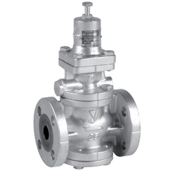 Reducing valve for steam Yoshitake GP-1000EN
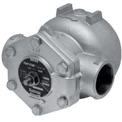 Float steam trap Yoshitake TSF-10
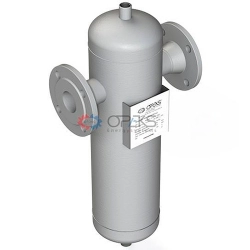 Centrifugal steam separator OPEKS-1-SC16-1-F50
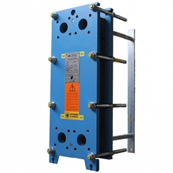 Plate heat exchanger THERMAKS РТА (GC)-16
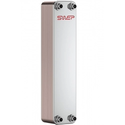 Brazed heat exchanger SWEP B25T
 Brazed heat exchanger SWEP B25THx20
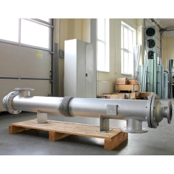 Shell and tube coolers
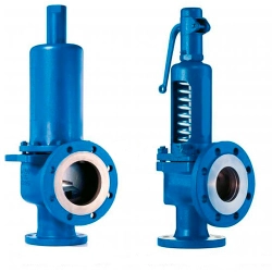 Safety valve LESER 441/442


