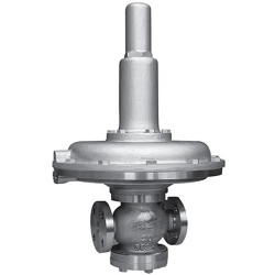
| Model | GD-400SS | |
| Nominal size | 15-25A | |
| Application | Air, nitrogen gas * 1 | |
| Inlet pressure | 2.5-400 kPa | |
| Lower. pressure | (A) 0.5-1.4 kPa (B) 1.2-3.3 kPa (C) 3.0-8.0 kPa (D) 7.0-20 kPa | |
| Working temperature | 5-60 ° C) | |
| Min. differential pressure | 2.0 kPa | |
| Max. coeff. pressure reduction | 400: 1 | |
| Low pressure measurement method | External impulse tube | |
| Minimum adjustable flow | 15-25A: 1.2 m³ / h (standard conditions) 32-50A: 10 m³ / h (standard conditions) | |
| Material | Frame | Cast stainless steel (SCS14) |
| Valve | Stainless steel | |
| Valve seat | Stainless steel | |
| Disk | Nitrile butadiene rubber * 3 | |
| Stock | Stainless steel | |
| Membrane | Nitrile butadiene rubber * 3 | |
| Compound | Flange connection JIS 10K FF | |
*1. For use with other fluids, the valve manufacturer should be consulted.
* 2 The cable (Ø8, length 2 m) and the connection for the external impulse pipe must be ordered separately.
* 3. Variants available with fluoroelastomer components. <
Installation example in a pipeline
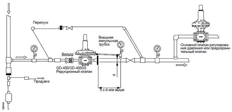
[Precautionary measures]
- Connect the external impulse line to the tap on the pipeline.
- The needle valve of the pressure reducing valve should not be adjusted.
- The diameter of the external impulse tube for measuring pressure should be capable of a fluid flow velocity of 5-15 m / s.
- Pressure values for crimping or checking the tightness of the pipeline are shown in the table to the right.
* If more pressure is applied, the internal parts of the valve may be damaged.

Flow characteristics graph
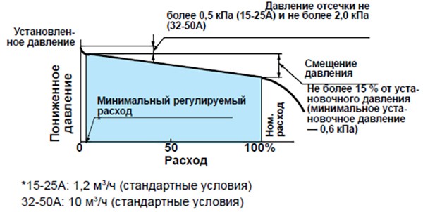
Technical characteristics graph
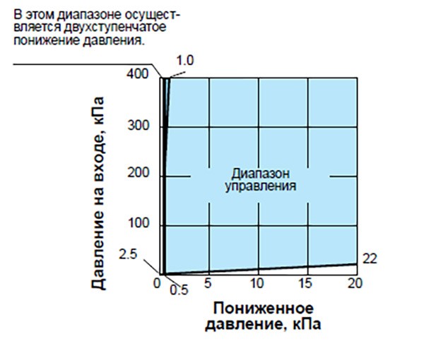
Pressure curve
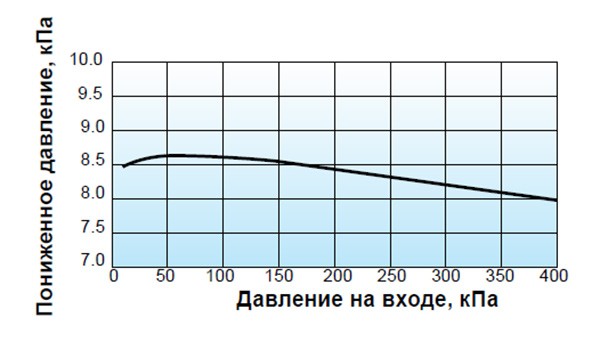
This graph shows the dependence of the reduced pressure when the pressure at the valve inlet changes from 400 kPa to 10 kPa at a set reduced pressure of 8.0 kPa.
- The pressure balanced design of the valve allows the reduced pressure to be kept constant without being influenced by the inlet pressure.
- The simple design makes the valve easy to disassemble for maintenance.
- Wide range of applications due to high working pressure.
- The large diaphragm area provides greater control accuracy for high set pressures.
| Nominal size | L | H 1 | H | The weight |
| 15A | 166 | 86 | 526 | 32.0 |
| 20A | 170 | 86 | 526 | 32.0 |
| 25A | 170 | 86 | 526 | 33.0 |
| 32A | 180 | 96 | 561 | 34.0 |
| 40A | 180 | 96 | 561 | 34.0 |
| 50A | 180 | 101 | 561 | 35.0 |

Sizing Chart (GD-400SS)
Inlet pressure from 2.5 kPa to 200 kPa (liquid: 20 ° C, air)

Example
Selection of the nominal size of the pressure reducing valve: inlet pressure (P1) - 10 kPa, outlet pressure (P2) - 3 kPa, flow rate - 15 m3 / h (standard conditions). First you need to find the intersection point (a) of the inlet pressure graph (P1) for 10 kPa with the outlet pressure graph (P2) for 3 kPa. From this point a line should be drawn down to the intersection (b) with a flow characteristic of 15 m3 / h (standard conditions). Since the intersection point (b) lies between the sizes 20A and 25A, the larger of the two, 25A, must be selected. * The safety factor should be assumed to be 80-90%.
Table 1. Inlet pressure from 200 kPa to 400 kPa
| Nominal size | Inlet pressure, kPa | Nominal flow rate (m 3 / h) (standard conditions) | |
| Reduced pressure, kPa | |||
| 0.5-4 | 4-20 | ||
| 15A | 200-400 | 60 | 60 |
| 20A | 200-300 | 90 | 90 |
| 300-400 | 90 | 120 | |
| 25A | 200-300 | 120 | 120 |
| 300-400 | 120 | 150 | |
| 400 | 120 | 190 | |
| 32A | 200-300 | 200 | 250 |
| 300-400 | 200 | 300 | |
| 40A | 200-300 | 250 | 275 |
| 300-400 | 250 | 325 | |
| 50A | 200-300 | 325 [275] | 375 [325] |
| 300-400 | 325 [275] | 425 [375] | |
* Flow rates in parentheses are for FKM model.
Delivery
- Pickup from a warehouse in Kiev - is free
- New Mail - at the rates of the delivery service, at the rates of the delivery service, at the rates of the delivery service
- SAT - at the rates of the delivery service
- Deliveri - at the rates of the delivery service
Payment
- Cashless payment with VAT
- Online Privat24, Visa / MasterCard

