

| Model | GPK-2001 | ||||
| Apply | Steam | ||||
| Reduced pressure sensing method | External impulse tube* | ||||
| Inlet pressure | JIS Rc JIS 20K RF | 0.1-2.0 MPa | 0.25-2.0 MPa | ||
| JIS 10KFF | 0.1-1.0 MPa | 0.25-1.0 MPa | |||
| Reduced pressure | 0.05-0.9 MPa (0.85 MPa for JIS 10K) | 0.2-1.4 MPa (0.85 MPa for JIS 10K) | |||
| Up to 85% of inlet pressure (gauge) | |||||
| Pneumatic load pressure | See pneumatic load pressure setting table | ||||
| Min. differential pressure | 0.05 MPa | ||||
| Max. coefficient pressure reduction | 20:1 | 10:1 | |||
| Max temperature | 220 °C | ||||
| Valve seat leaks | No more than 0.01% of nominal flow | ||||
| Material | Body | Ductile iron | |||
| Main valve | Stainless steel | ||||
| Valve seat | Stainless steel | ||||
| Pilot | Stainless steel | ||||
| Pilot Seat | Stainless steel | ||||
| Membrane | Stainless steel | ||||
| Reduced pressure impulse tube | Copper pipe | ||||
| Connection | Threaded JIS Rc Flanged JIS 20K RF and 10K FF | ||||
*Standard external impulse tube. When installing the pressure reducing valve, be sure to connect the impulse tube and compensator supplied in the kit. If the impulse pipe is not connected, the valve will not work. (Various specifications are available with internal impulse piping. Please note that the Cv value of the internal impulse piping is lower than that of the external impulse piping.)
Available with ASME or EN flanges.
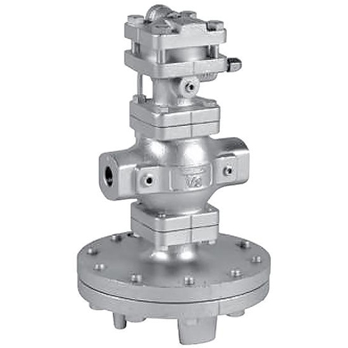
Diaphragm valve with "pilot" high precision low pressure control. This option is optimal if pressure surges significantly affect quality.
- Superior to plunger type valve in capacity and performance, effective in controlling inlet pressure and flow fluctuations.
- The spherical main valve provides good sealing and reduced leakage from the valve seat (according to ANSI Class IV).
- Easy pressure adjustment due to remote control; wide range of pressure settings.
- GPK-2001 and GPK-2003 can be selected according to pneumatic load pressure.
GPK-2001 with threaded connection
| Nom. size | d | L | H1 | H | A | Weight |
|---|---|---|---|---|---|---|
| 15A | Rc 1/2 | 150 | 170 | 335 | 200 | 14.0 |
| 20A | Rc 3/4 | 150 | 170 | 335 | 200 | 14.0 |
| 25A | Rc 1 | 160 | 175 | 341 | 226 | 18.5 |
| 32A | Rc 1-1/4 | 180 | 192 | 371 | 226 | 21.5 |
| 40A | Rc 1-1/2 | 180 | 192 | 371 | 226 | 21.5 |
| 50A | Rc 2 | 230 | 216 | 435 | 276 | 33.0 |
* Available with NPT connection.

GPK-2001 with flange connection (JS 20KRF)
| Nom. size | L | H1 | H | A | Weight |
|---|---|---|---|---|---|
| 15A | 146 (142) | 170 | 335 | 200 | 15.5 (15.3) |
| 20A | 146 (142) | 170 | 335 | 200 | 16.0 (15.8) |
| 25A | 156 (152) | 175 | 341 | 226 | 21.0 (20.6) |
| 32A | 176 (172) | 192 | 371 | 226 | 24.0 (23.4) |
| 40A | 196 (192) | 192 | 371 | 226 | 24.5 (24.1) |
| 50A | 222 (218) | 216 | 435 | 276 | 36.0 (35.8) |
| 65A | 282 (278) | 251 | 489 | 352 | 64.5 (64.2) |
| 80A | 302 (294) | 264 | 512 | 352 | 71.5 (69.3) |
| 100A | 342 (330) | 321 | 595 | 401 | 111.0 (107.4) |
* The above values in brackets are dimensions and weights for JIS 10K FF flange connections.
*Contact us for specs.
")
GPK-2001 Specification Selection Chart

See Refer to the selection chart above to select the most suitable pressure reducing valve option. Find the point of intersection between the inlet pressure (P1) and the reduced pressure (P2). If the crossover point is within range (A), the pressure reduction should be carried out in two steps. If within the range (B) - the control range. If within range (C), maximum performance cannot be achieved. When depressurizing in two stages, the distance between the valves must be at least 3 m.
Sizing Chart for GP-2000 Series (Steam, External Impulse Tube)
")
Example.
When sizing a pressure reducing valve at inlet pressure (P1), reduced pressure (P2) and flow rate of 0.6 MPa, 0.4 MPa and 600 kg/h, respectively, first find the intersection point (a) of the pressure lines at the inlet 0.6 MPa and reduced pressure 0.4 MPa. From this point, draw a line downward until it intersects with the line corresponding to a flow rate of 600 kg/h — intersection point (b). Since the point of intersection (b) lies between the dimensions 20A and 25A, it is necessary to choose the larger of the two — 25A.
*The margin factor should be taken equal to 80-90%.
Flow curve

When selecting a nominal size, set the flow rate to 80-90% of the design flow so that the pressure loss and temperature loss of the shut-off valve, filter, etc., before or after the pressure reducing valve can be used. In order for the pressure reducing valve to exhibit maximum flow characteristics, do not select a small diameter pipeline as a countermeasure against the influence of resistance in the pipe. Select a nominal size based on the nominal size selection chart.
GPK-2001 pressure curve plot

This graph shows the change in underpressure when the 1.75MPa inlet pressure begins to fluctuate between 0.2MPa and 2.0MPa, while the underpressure is set at 0.14 MPa.
GPK-2001 Pneumatic Load Pressure Setting Table

As a rule, the pneumatic load setting corresponds to the data in the table above. Pressure settings vary slightly depending on operating conditions. For actual use, adjust the pneumatic load pressure according to the desired pressure setting value.
Delivery
- Pickup from a warehouse in Kiev - is free
- New Mail - at the rates of the delivery service, at the rates of the delivery service, at the rates of the delivery service
- SAT - at the rates of the delivery service
- Deliveri - at the rates of the delivery service
Payment
- Cashless payment with VAT
- Online Privat24, Visa / MasterCard


