| Model | |||||
| Apply | Steam | ||||
| Downspan Perception Method pressure | Outer impulse tube* | ||||
| Max inlet pressure | 3.0 MPa | 1.0 MPa | 2.0 MPa | 3.0 MPa | |
| Reduced Pressure | 0.02-0.15 MPa 0.1-1.4 MPa 1.3-2.0 MPa | 0.02-0.15 MPa 0.1-0.85 MPa | 0.02-0.15 MPa 0.1-1.4 MPa 1.3-1.7 MPa | 0.02-0.15 MPa 0.1-1.4 MPa 1.3-2.0 MPa | |
| Maximum 85% inlet pressure (gauge) | |||||
| Min. differential pressure | 0.05 MPa | ||||
| Max. coefficient pressure reduction | 20:1 | ||||
| Max temperature | 260 °C | ||||
| Valve seat leaks | No more than 0.01% of nominal flow | ||||
| Material | Body | Cast carbon steel | |||
| Head. valve, valve seat | Stellite coated stainless steel | ||||
| Pilot valve, pilot valve seat | Stainless steel | ||||
| Membrane | Stainless steel | ||||
| Connection | JIS Rc threaded connection | JIS 10K FF flanged | JIS 20K RF flange connection | JIS 30K RF flange connection connection | |
*Requires impulse tube. The compensator size is shown below:
JIS Rc, JIS SW, JIS 10K FF, 20K RF and 30K RF:Rc1/4
NPT, ASME Class 150 and 300: NPT 1/4
The length of the impulse tube must be less than 5m.
When installing a pressure reducing valve, be sure to attach the impulse tube and compensator. If the impulse tube is not connected, the valve will not work.
*Socket weld (SW) options available for 15-50A.
* Available with ASME or EN flanges.
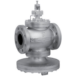
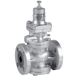
Diaphragm valve with "pilot" high precision low pressure control. This option is optimal if pressure surges significantly affect quality.
- GP-2000CS series pressure reducing valve - valve with "pilot" diaphragm-type control, through which a larger volume flow can be controlled than with a plunger-type valve. It provides greater control over pressure changes on the inlet side or load changes on the outlet side.
- The built-in 200 mesh filter prevents most of the problems caused by deposits in the pilot valve.
- Spherical valve provides an ANSI Class IV tight seal.
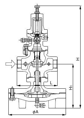
JIS Rc with threaded connection
| Nom. size | d | L | H | H1 | Weight |
|---|---|---|---|---|---|
| 15A | Rc 1/2 | 150 | 398 | 170 | 16 |
| 20A | Rc 3/4 | 150 | 398 | 170 | 16 |
| 25A | Rc 1 | 160 | 404 | 175 | 21.5 |
| 32A | Rc 1-1/4 | 180 | 434 | 192 | 24 |
| 40A | Rc 1-1/2 | 180 | 434 | 192 | 24 |
| 50A | Rc 2 | 230 | 498 | 216 | 37 |
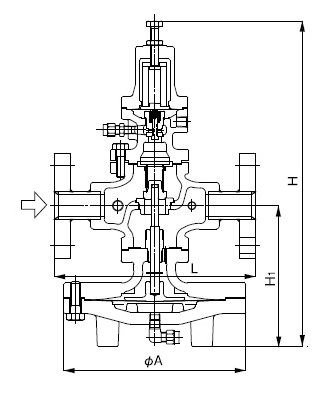
Flanged JIS 30K RF
| Nom. size | L | H | H1 | Weight |
|---|---|---|---|---|
| 50A | 230 | 498 | 216 | 42 |
| 65A | 294 | 552 | 251 | 75 |
| 80A | 314 | 575 | 264 | 84 |
| 100A | 358 | 658 | 321 | 133 |

With welded flange
| Nom. size | L | H | H1 | A | Weight |
|---|---|---|---|---|---|
| 15A | 240 | 398 | 170 | 200 | 18.0 |
| 20A | 240 | 398 | 170 | 200 | 18.0 |
| 25A | 250 | 404 | 175 | 226 | 24.5 |
| 32A | 260 | 434 | 192 | 226 | 27.0 |
| 40A | 260 | 434 | 192 | 226 | 27.0 |
| 50A | 320 | 498 | 216 | 276 | 40.0 |
Specification Chart
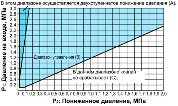
Based on the diagram above, select the most appropriate pressure reducing valve. First find the point of intersection of inlet pressure (P1) and reduced pressure (P2) on the selection diagram. A two-stage pressure reduction is required if the cross point is within range (A), or the pressure is controlled by a single pressure reducing valve if the cross point is within range (B). In this range, the valve does not work (C). To apply two-stage pressure reduction, the two pressure reducing valves must be placed as far apart as possible.
Flow curve
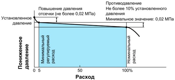
When choosing a nominal size, set the flow rate to 80-90% of the design flow so that pressure loss and temperature loss of the shutoff valve, filter, etc. can be used. before or after the pressure reducing valve. In order for the pressure reducing valve to exhibit maximum flow characteristics, do not select a small diameter pipeline as a countermeasure against the influence of resistance in the pipe. Select a nominal size based on the nominal size selection chart.
Pressure Plot
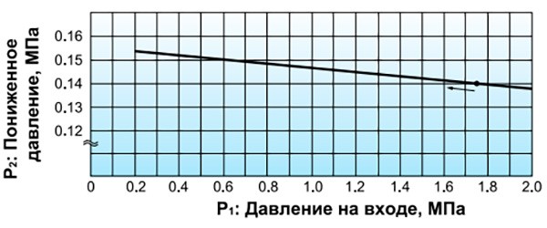
This graph shows the change in underpressure when the 1.75MPa inlet pressure begins to fluctuate between 0.2MPa and 2.0MPa, while the underpressure is set at 0.14 MPa.
Relief valve pressure setting for emergency use on outlet side of steam reducing valve
| Reducing valve pressure setting (MPa) | Relief valve pressure setting (MPa) |
|---|---|
| 0.1 or less | Reducing valve pressure setting +0.05 or more |
| 0.11-0.4 | Reducing valve pressure setting +0.08 or more |
| 0.41-0.6 | Reducing valve pressure setting +0.1 or more |
| 0.61-0.8 | Reducing valve pressure setting +0.12 or more |
| More than 0.8 | Reducing valve pressure setting +15% |
If a relief valve is installed at the outlet of the pressure reducing valve for emergency use and no laws or regulations apply, the capacity of the relief valve should be about 10% of the maximum flow pressure reducing valve.
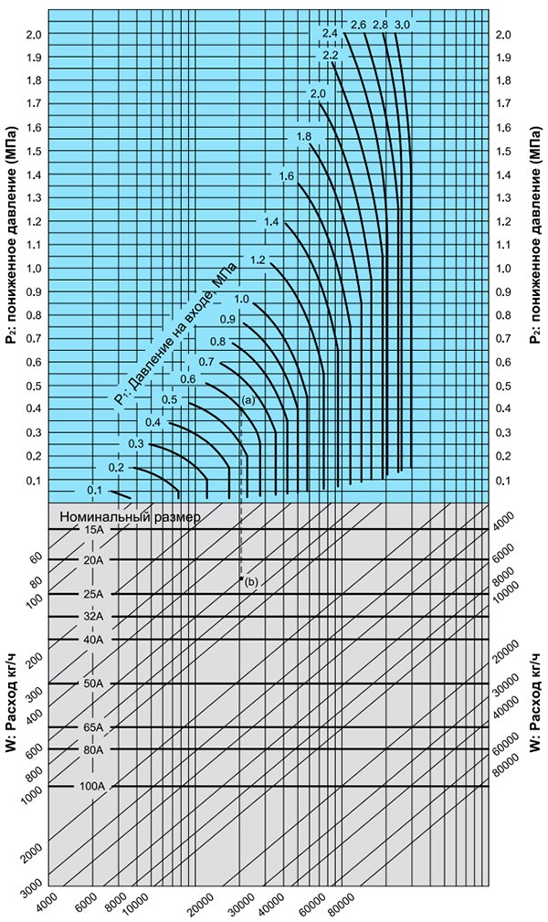
Nominal sizing chart (for steam)
Example.
When sizing a pressure reducing valve at inlet pressure (P1), reduced pressure (P2) and flow rate of 0.6 MPa, 0.4 MPa and 600 kg/h respectively, first find the intersection point (a) of the pressure lines at the inlet 0.6 MPa and reduced pressure 0.4 MPa. From this point, draw a line downward until it intersects with the line corresponding to a flow rate of 600 kg/h — intersection point (b). Since the point of intersection (b) lies between the dimensions 20A and 25A, it is necessary to choose the larger of the two — 25A. the safety factor should be taken equal to 80-90%.
Delivery
- Pickup from a warehouse in Kiev - is free
- New Mail - at the rates of the delivery service, at the rates of the delivery service, at the rates of the delivery service
- SAT - at the rates of the delivery service
- Deliveri - at the rates of the delivery service
Payment
- Cashless payment with VAT
- Online Privat24, Visa / MasterCard

