Coil Specifications
| Rated voltage | Change voltage AC 100 V (50/60 Hz, optional) | The coils for AC 100 V and AC 200 V are different | ||
| Change voltage AC 200 V (50/60 Hz, optional) | ||||
| Permissible fluctuations | Rated voltage: -15% to + 10% | |||
| Degree of protection | IP67 | |||
| Cable wiring | G1 / 2 conduit connection | |||
| Electr. cable | When connecting a 3.5 mm conduit1 | |||
| Pace. surrounded Wednesday | 5-60 ° C | |||
| Voltage and current | Voltage (V) / Frequency (Hz) | Starting current (A) | Excitation current (A) | |
| 100/50 | 0.27 | 0.16 | ||
| 100/60 | 0.25 | 0.13 | ||
| 200/50 | 0.14 | 0.08 | ||
| 200/60 | 0.13 | 0.07 | ||
| Insulation class | Class H | |||
| Protective structure | Tightness and explosion protection (explosion protection code d2G4) | Conformity number: T21092 | ||
| Insulation resistance | Not less than 100 MOhm (cold) | |||
| Withstand voltage | Change voltage AC 100 V: AC voltage AC 200 V: AC voltage AC 2000 V / min. voltage AC 2400 V / min | |||
Specifications
| Application | Air, nitrogen | Cold and hot water, heavy and light oil products | |
| Fluid viscosity | Not more than 50 cSt | ||
| Operating pressure | 0.05-0.9 MPa | 0.05-1.6 MPa | |
| Evacuation is not allowed | |||
| Min. differential pressure | 0.05 MPa | ||
| Liquid temperature | 5-60 ° C | ||
| Principle | Normally closed | ||
| Material | Frame | Brass (C3771) | |
| Main valve | Brass (C3604) | ||
| Gate | Fluoroelastomer | ||
| Compound | JIS Rc Threaded Connection | ||
DP-34N (optional)
Sealed gland
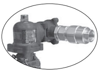
Use a cable gland for the cable outlet. Slide the gland onto the threads 5. First, tighten the gland with the nut as tight as possible, then tighten the packing gland and close the cable.
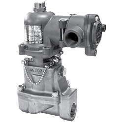
The solenoid valve is opened and closed by moving a steel element called a plunger under the influence of solenoid electromagnetic forces and is used to control the flow of fluid in pipelines (open-close control).
- Suitable for use in hazardous areas (zones 1 and 2).
- Can be installed horizontally or vertically.
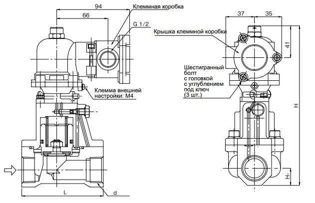
| Nom. the size | d | L | H 1 | H | The weight |
| 15A | Rc 1/2 | 85 | 14.5 | 173 | 2.2 |
| 20A | Rc 3/4 | 95 | 17 | 190 | 2.7 |
| 25A | Rc 1 | 105 | 22 | 210 | 3.5 |
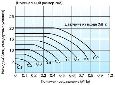
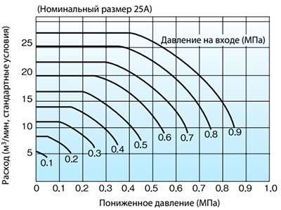
Nominal sizing diagram (for air)

How to use diagrams
If the flow rate is 5 m3 / min (standard conditions), the inlet pressure (P1) is 0.7 MPa, the outlet pressure (P2) is 0.5 MPa, find the intersection point (a) of the lines P1 = 0.7 MPa and Р 2 = 0.5 MPa in the left diagram. Point (a) indicates a flow rate of about 6 m3 / min, which is greater than an operating flow rate of 5 m3 / min, so 15A would be a suitable size. If the flow rate is below the working flow rate, consider the 20A or 25A sizes.
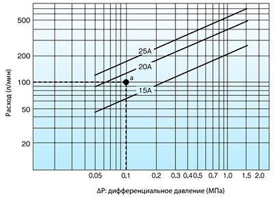
Nominal sizing diagram (for water)
How to use diagrams
If the inlet pressure is 0.4 MPa, the outlet pressure is 0.3 MPa, and the flow rate is 100 l / min, find the intersection point (a) of the differential pressure lines (∆Р = 0.1 MPa) and the flow rate of 100 l / min. Since this intersection point (a) lies between dimensions 15A and 20A, choose the larger of the two, 20A.
Delivery
- Pickup from a warehouse in Kiev - is free
- New Mail - at the rates of the delivery service, at the rates of the delivery service, at the rates of the delivery service
- SAT - at the rates of the delivery service
- Deliveri - at the rates of the delivery service
Payment
- Cashless payment with VAT
- Online Privat24, Visa / MasterCard

